
Product Introduction
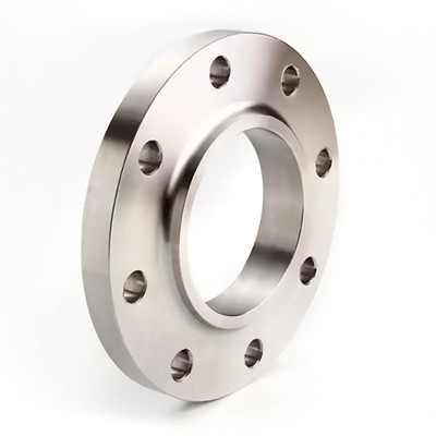
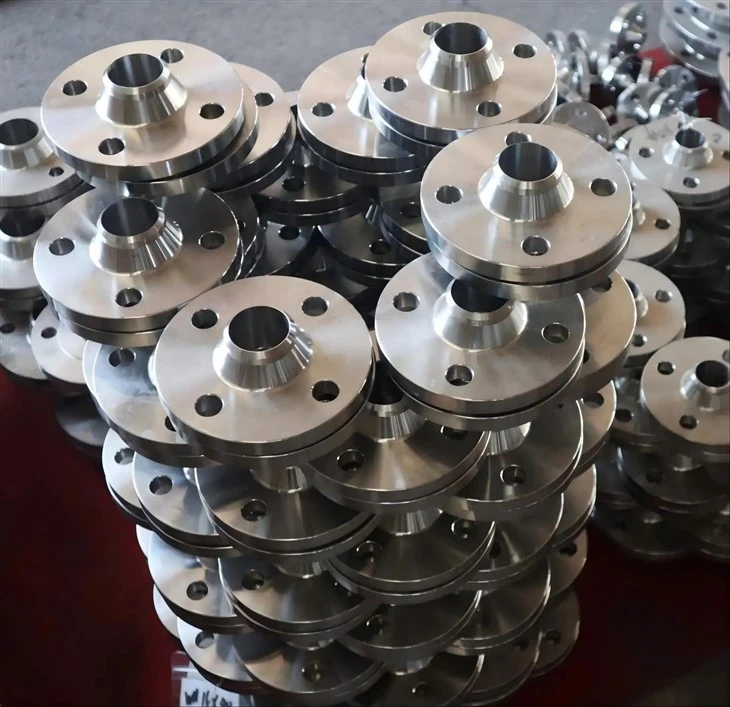
The EN Weld Neck Flange is designed with a tapered hub that provides smooth stress distribution at the flange-pipe junction, making it suitable for high-pressure and high-temperature applications. Available in pressure ratings from PN2.5 to PN400 and sizes from DN10 to DN4000, these flanges accommodate various wall thicknesses and pipe schedules. With a monthly supply capacity of 2,000 tons, HAIHAO ensures consistent availability for large-scale industrial projects across oil and gas, power generation, and chemical processing sectors.


Specifications
● Standard: EN 1092-1 Type 11 (Forged, Weld Neck)
● Size Range: DN10 to DN4000
● Pressure Ratings: PN2.5, PN6, PN10, PN16, PN25, PN40, PN63, PN100, PN160, PN250, PN320, PN400
● Materials:
○ Carbon Steel: P250GH, P245GH, P280GH, P355NH
○ Alloy Steel: 13CrMo4-5, 11CrMo9-10, X10CrMoVNb9-1
○ Stainless Steel: X2CrNi18-9, X6CrNiTi18-1, X2CrNiMo17-12-2
● Connection Type: Butt-welding end, bolted connection
● Facing Types: Type 01, 02, 04, 05, 11, 12, 13, 21, 32, 34, 35, 36, 37
● Surface Treatment: Rust preventive oil, hot-dip galvanizing, sandblasting, acid washing
● Packaging: Wooden crates or pallets
Dimensions

|
EN 1092-1 PN10 Flanges |
||||||||||||||||||||||||||||||||
|
DN |
Mating dimensions |
Diameter of Neck |
Bore |
Flange |
Chamfer |
Collar thickness |
Diameter of Shoulders |
Length |
Neck |
CornerRadius |
Wall thickness |
|||||||||||||||||||||
|
Diameter Outside |
Diameter of Bolt Circle |
BoltHole |
Bolting |
|||||||||||||||||||||||||||||
|
D |
K |
L |
No |
Size |
A |
B1 |
B2 |
B3 |
C1 |
C2 |
C3 |
C4 |
E |
F |
G |
H1 |
H2 |
H3 |
H4 |
H5 |
N1 |
N2 |
N3 |
R1 |
S |
|||||||
|
Flange type |
||||||||||||||||||||||||||||||||
|
01,02,04,05,11,12,13,21 |
11 |
01 |
02 |
04 |
01 |
11 |
21 |
05 |
02 |
32 |
35 |
36 |
37 |
05 |
12 |
11 |
11 |
35 |
36 |
37 |
11 |
12 |
21 |
11 |
34 |
11 |
||||||
|
10 |
90 |
60 |
14 |
4 |
M12 |
17.2 |
18.0 |
21 |
31 |
14 |
16 |
16 |
16 |
3 |
12 |
5 |
2.0 |
2.5 |
- |
22 |
35 |
6 |
35 |
35 |
7 |
28 |
30 |
28 |
4 |
1.8 |
See "Wall thickness and end preparation" |
|
|
15 |
95 |
65 |
14 |
4 |
M12 |
21.3 |
22.0 |
25 |
35 |
14 |
16 |
16 |
16 |
3 |
12 |
5 |
2.0 |
2.5 |
- |
22 |
38 |
6 |
38 |
38 |
7 |
32 |
35 |
32 |
4 |
2.0 |
||
|
20 |
105 |
75 |
14 |
4 |
M12 |
26.9 |
27.5 |
31 |
42 |
16 |
18 |
18 |
18 |
4 |
14 |
6 |
2.5 |
3.0 |
- |
26 |
40 |
6 |
40 |
40 |
8 |
40 |
45 |
40 |
4 |
2.3 |
||
|
25 |
115 |
85 |
14 |
4 |
M12 |
33.7 |
34.5 |
38 |
49 |
16 |
18 |
18 |
18 |
4 |
14 |
7 |
2.5 |
3.0 |
- |
28 |
40 |
6 |
40 |
40 |
10 |
46 |
52 |
50 |
4 |
2.6 |
||
|
32 |
140 |
100 |
18 |
4 |
M16 |
42.4 |
43.5 |
47 |
59 |
18 |
18 |
18 |
18 |
5 |
14 |
8 |
3.0 |
3.0 |
- |
30 |
42 |
6 |
42 |
42 |
12 |
56 |
60 |
60 |
6 |
2.6 |
||
|
40 |
150 |
110 |
18 |
4 |
M16 |
48.3 |
49.5 |
53 |
67 |
18 |
18 |
18 |
18 |
5 |
14 |
8 |
3.0 |
3.0 |
- |
32 |
45 |
7 |
45 |
45 |
15 |
64 |
70 |
70 |
6 |
2.6 |
||
|
50 |
165 |
125 |
18 |
4 |
M16 |
60.3 |
61.5 |
65 |
77 |
20 |
18 |
18 |
18 |
5 |
16 |
8 |
3.0 |
4.0 |
- |
28 |
45 |
8 |
45 |
45 |
20 |
74 |
84 |
84 |
6 |
2.9 |
||
|
65 |
185 |
145 |
18 |
8 |
M16 |
76.1 |
77.5 |
81 |
96 |
20 |
18 |
18 |
18 |
6 |
16 |
8 |
3.0 |
4.0 |
55 |
32 |
45 |
10 |
45 |
45 |
20 |
92 |
104 |
104 |
6 |
2.9 |
||
|
80 |
200 |
160 |
18 |
8 |
M16 |
88.9 |
90.5 |
94 |
108 |
20 |
20 |
20 |
20 |
6 |
16 |
10 |
3.0 |
4.0 |
70 |
34 |
50 |
10 |
50 |
50 |
25 |
105 |
118 |
120 |
6 |
3.2 |
||
|
100 |
220 |
180 |
18 |
8 |
M16 |
114.3 |
116.0 |
120 |
134 |
22 |
20 |
20 |
20 |
6 |
18 |
10 |
4.0 |
4.0 |
90 |
40 |
52 |
12 |
52 |
52 |
25 |
131 |
140 |
140 |
8 |
3.6 |
||
|
125 |
250 |
210 |
18 |
8 |
M16 |
139.7 |
141.5 |
145 |
162 |
22 |
22 |
22 |
22 |
6 |
18 |
10 |
4.0 |
4.0 |
115 |
44 |
55 |
12 |
55 |
55 |
25 |
156 |
168 |
170 |
8 |
4.0 |
||
|
150 |
285 |
240 |
22 |
8 |
M20 |
168.3 |
170.5 |
174 |
188 |
24 |
22 |
22 |
22 |
6 |
20 |
10 |
4.0 |
4.0 |
140 |
44 |
55 |
12 |
55 |
55 |
25 |
184 |
195 |
190 |
10 |
4.5 |
||
|
200 |
340 |
295 |
22 |
8 |
M20 |
219.1 |
221.5 |
226 |
240 |
24 |
24 |
24 |
24 |
6 |
20 |
11 |
5.0 |
5.0 |
190 |
44 |
62 |
16 |
62 |
62 |
30 |
234 |
246 |
246 |
10 |
6.3 |
||
|
250 |
395 |
350 |
22 |
12 |
M20 |
273.0 |
276.5 |
281 |
294 |
26 |
26 |
26 |
26 |
8 |
22 |
12 |
8.0 |
- |
235 |
46 |
68 |
16 |
68 |
68 |
- |
292 |
298 |
298 |
12 |
6.3 |
||
|
300 |
445 |
400 |
22 |
12 |
M20 |
323.9 |
327.5 |
333 |
348 |
26 |
26 |
26 |
26 |
8 |
22 |
12 |
8.0 |
- |
285 |
46 |
68 |
16 |
68 |
68 |
- |
342 |
350 |
348 |
12 |
7.1 |
||
|
350 |
505 |
460 |
22 |
16 |
M20 |
355.6 |
359.5 |
365 |
400 |
30 |
26 |
26 |
26 |
8 |
22 |
13 |
8.0 |
- |
330 |
53 |
68 |
16 |
68 |
68 |
- |
385 |
400 |
408 |
12 |
7.1 |
||
|
400 |
565 |
515 |
26 |
16 |
M24 |
406.4 |
411.0 |
416 |
450 |
32 |
26 |
26 |
26 |
8 |
24 |
14 |
8.0 |
- |
380 |
57 |
72 |
16 |
72 |
72 |
- |
440 |
456 |
456 |
12 |
7.1 |
||
|
450 |
615 |
565 |
26 |
20 |
M24 |
457.0 |
462.0 |
467 |
498 |
36 |
28 |
28 |
28 |
8 |
24 |
15 |
- |
- |
425 |
63 |
72 |
16 |
72 |
- |
- |
488 |
502 |
502 |
12 |
7.1 |
||
|
500 |
670 |
620 |
26 |
20 |
M24 |
508.0 |
513.5 |
519 |
550 |
38 |
28 |
28 |
28 |
8 |
26 |
16 |
- |
- |
475 |
67 |
75 |
16 |
75 |
- |
- |
542 |
559 |
559 |
12 |
7.1 |
||
|
600 |
780 |
725 |
30 |
20 |
M27 |
610.0 |
616.5 |
622 |
650 |
42 |
30 |
34 |
34 |
8 |
26 |
18 |
- |
- |
575 |
75 |
82 |
18 |
80 |
- |
- |
642 |
658 |
658 |
12 |
- |
||
|
700 |
895 |
840 |
30 |
24 |
M27 |
711.0 |
** |
721 |
- |
50 |
35 |
** |
38 |
8 |
- |
20 |
- |
- |
670 |
- |
85 |
18 |
80 |
- |
- |
746 |
- |
772 |
12 |
- |
||
|
800 |
1015 |
950 |
33 |
24 |
M30 |
813.0 |
824 |
- |
56 |
38 |
48 |
8 |
- |
20 |
- |
- |
770 |
- |
96 |
18 |
90 |
- |
- |
850 |
- |
876 |
12 |
- |
||||
|
900 |
1115 |
1050 |
33 |
28 |
M30 |
914.0 |
926 |
- |
62 |
38 |
50 |
8 |
- |
22 |
- |
- |
860 |
- |
99 |
20 |
95 |
- |
- |
950 |
- |
976 |
12 |
- |
||||
|
1000 |
1230 |
1160 |
36 |
28 |
M33 |
1016 |
1028 |
- |
70 |
44 |
54 |
8 |
- |
24 |
- |
- |
960 |
- |
105 |
20 |
95 |
- |
- |
1052 |
- |
1080 |
16 |
- |
||||
|
1200 |
1455 |
1380 |
39 |
32 |
M36 |
1219 |
1234 |
- |
83 |
55 |
66 |
8 |
- |
26 |
- |
- |
1160 |
- |
132 |
25 |
115 |
- |
- |
1256 |
- |
1292 |
16 |
- |
||||
|
1400 |
1675 |
1590 |
42 |
36 |
M39 |
1422 |
- |
- |
- |
** |
65 |
- |
- |
- |
- |
- |
- |
- |
- |
143 |
25 |
- |
- |
- |
1460 |
- |
1496 |
16 |
- |
|||
|
1600 |
1915 |
1820 |
48 |
40 |
M45 |
1626 |
- |
- |
- |
75 |
- |
- |
- |
- |
- |
- |
- |
- |
159 |
25 |
- |
- |
- |
1666 |
- |
1712 |
16 |
- |
||||
|
1800 |
2115 |
2020 |
48 |
44 |
M45 |
1829 |
- |
- |
- |
85 |
- |
- |
- |
- |
- |
- |
- |
- |
175 |
30 |
- |
- |
- |
1868 |
- |
1910 |
16 |
- |
||||
|
2000 |
2325 |
2230 |
48 |
48 |
M45 |
2032 |
- |
- |
- |
90 |
- |
- |
- |
- |
- |
- |
- |
- |
- |
186 |
30 |
- |
- |
- |
2072 |
- |
2120 |
16 |
- |
|||
|
2200 |
2550 |
2440 |
56 |
52 |
M52 |
2235 |
- |
- |
|
100 |
- |
- |
- |
- |
- |
- |
- |
- |
- |
202 |
35 |
- |
- |
- |
2275 |
- |
- |
18 |
- |
|||
|
2400 |
2760 |
2650 |
56 |
56 |
M52 |
2438 |
- |
- |
- |
110 |
- |
- |
- |
- |
- |
- |
- |
- |
- |
218 |
35 |
- |
- |
- |
2478 |
- |
- |
18 |
- |
|||
|
2600 |
2960 |
2850 |
56 |
60 |
M52 |
2620 |
- |
- |
- |
110 |
- |
- |
- |
- |
- |
- |
- |
- |
- |
224 |
40 |
- |
- |
- |
2680 |
- |
- |
18 |
- |
|||
|
2800 |
3180 |
3070 |
56 |
64 |
M52 |
2820 |
- |
- |
- |
124 |
- |
- |
- |
- |
- |
- |
- |
- |
- |
244 |
40 |
- |
- |
- |
2882 |
- |
- |
18 |
- |
|||
|
3000 |
3405 |
3290 |
62 |
68 |
M56 |
3020 |
- |
- |
|
132 |
- |
- |
- |
- |
- |
- |
- |
- |
- |
257 |
45 |
- |
- |
- |
3085 |
- |
- |
18 |
- |
|||
Features
- Material Traceability: Each EN Weld Neck Flange is forged from certified grades such as P250GH (yield strength ≥235 MPa at ambient temperature) or 13CrMo4-5 (high-temperature creep resistance), ensuring mechanical properties comply with EN10222 specifications.
- Precision-Machined Dimensions: Bolt hole diameters (L) are held to H14 tolerances, and bolt circle diameters (K) are concentric within 0.5mm, ensuring proper alignment during field assembly.
- Multiple Facing Options: Available with raised face (f1=2-4mm), RTJ grooves (w, x, y dimensions as per table), and tongue-and-groove finishes to accommodate various gasket types and pressure requirements.
- Schedule-Matched Neck: Neck outside diameter (A) is forged to match standard pipe dimensions-for example, DN200 PN10 flanges feature A=219.1mm for seamless butt-weld integration with schedule pipes.
- Corrosion Protection: Standard rust-preventive oil coating meets ISO 9227 salt spray resistance for 72 hours; hot-dip galvanizing available for marine environments.
Applications
Oil & Gas
Pipeline connections, valve assemblies, and processing equipment operating up to PN400
01
Power Generation
Boiler feedwater systems, steam turbines, and heat exchangers requiring high-temperature alloys like 13CrMo4-5
02
Chemical Processing
Reactors and storage tanks using stainless steel grades X2CrNi18-9 or X2CrNiMo17-12-2 for corrosion resistance
03
Marine Engineering
Shipbuilding and offshore platforms requiring hot-dip galvanized surface treatment
04
Municipal Infrastructure
Water supply networks (PN10-PN16), heating systems, and gas distribution pipelines
05
FAQ
Hot Tags: en weld neck flange, China en weld neck flange manufacturers, suppliers, factory, blind plate flange, 4 inch weld neck flange, flanges, EN Slip on Flange, flange collar, standard pipe flange